| As mentioned, the sender is accessed by peeling back the trunk carpet and sound insulation pad (on the right-hand side), then removing the black plastic cap that covers the sender itself (the black cap is held in place by the carpet, mainly). Shown to the right is the example of a later car, an 82 931, where the sender is bolted to the tank by 5 5mm allen head bolts. Earlier cars used a type of sender that screws into the tank; the factory mechanics had a special tool to install and remove this sender, but usually pliers or a large slip-joint wrench can be made to work. | 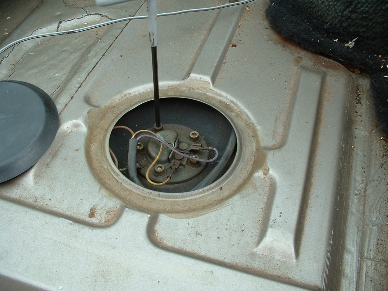 |
| Once the bolts are removed, or the sender is unscrewed, the sender is removed. GRADUALLY! The sender is filled and emptied in the tank through very small holes, so as to prevent the reading from jumping around. This does mean, however, that the sender is full of gas and will take a good number of minutes to drain! Another reason to perform this with a relatively empty tank. Note in the picture on the right that the varnish coating can already be seen on the bottom half of the sender. | 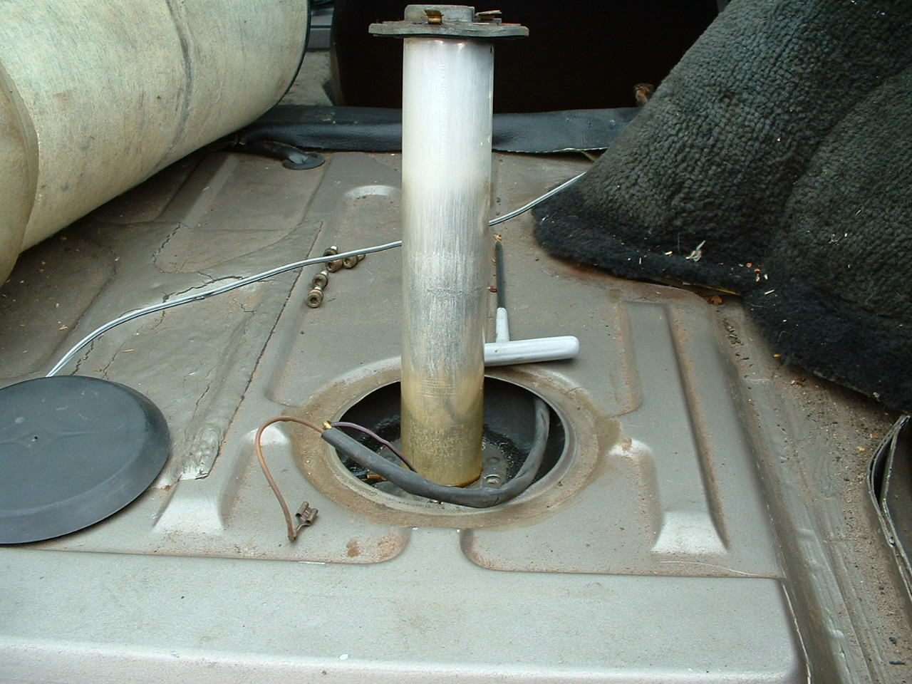 |
| Once the sender is removed, it must be disassembled. On this later sender, the bottom half of the unit is held on by a small nut, which looks as if it should take a flat-head screwdriver. Only problem is that the center is obscured. This is a standard form of tamperproofing. The solution is simply to buy a cheap flat-head screwdriver and grind out the center using a die grinder, file or the like. The resulting tool and the nut are shown to the right. This tool also comes in handy for removing spoilers, secured with the same fastener. | 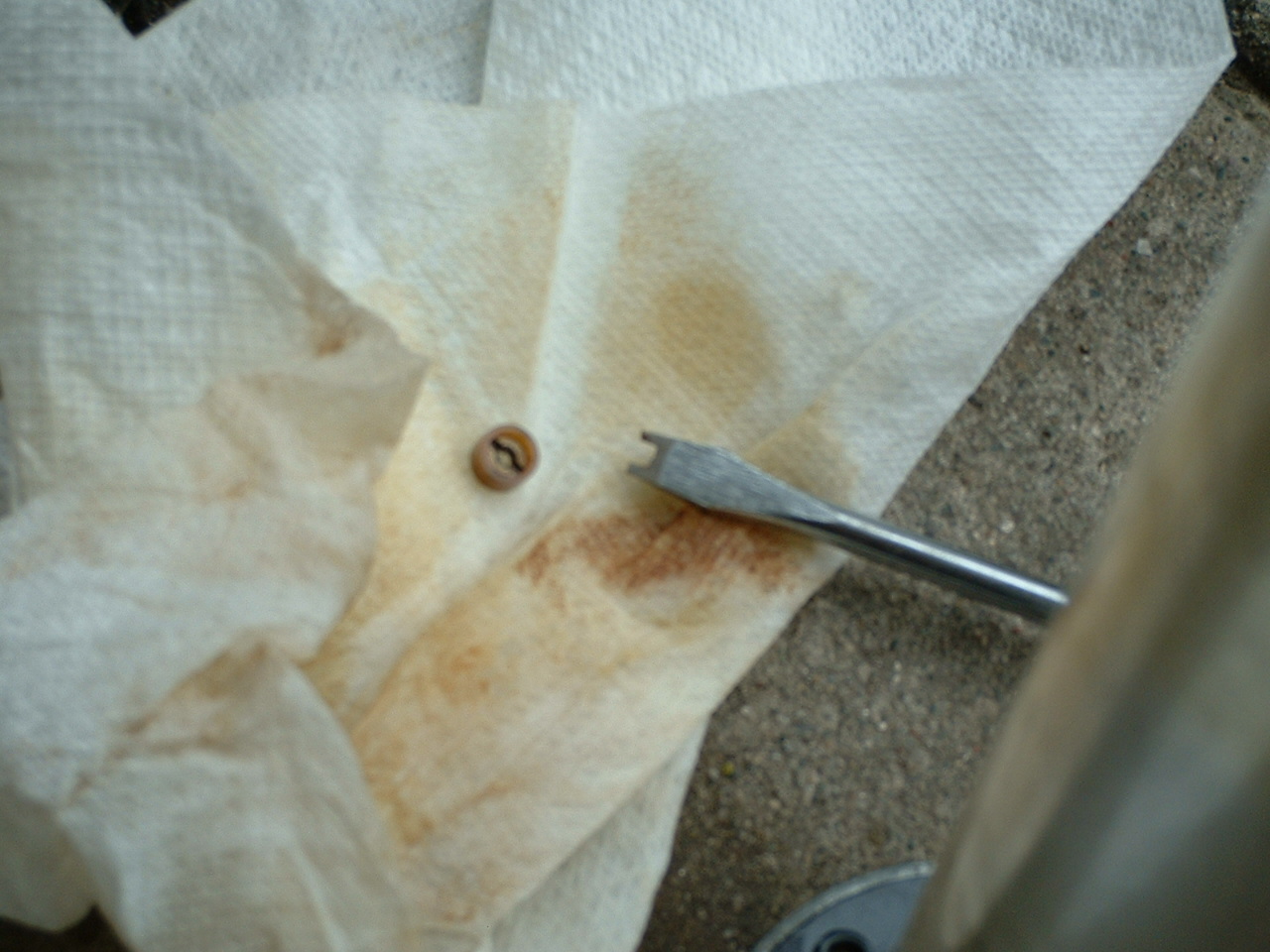 |
| The end plate of the sender is here shown removed (from the bottom of the sender), next to the sender and nut. The convoluted path for fuel to follow to drain in and out of the sender can be clearly seen, as can varnish and rust from 20+ years of neglect. | 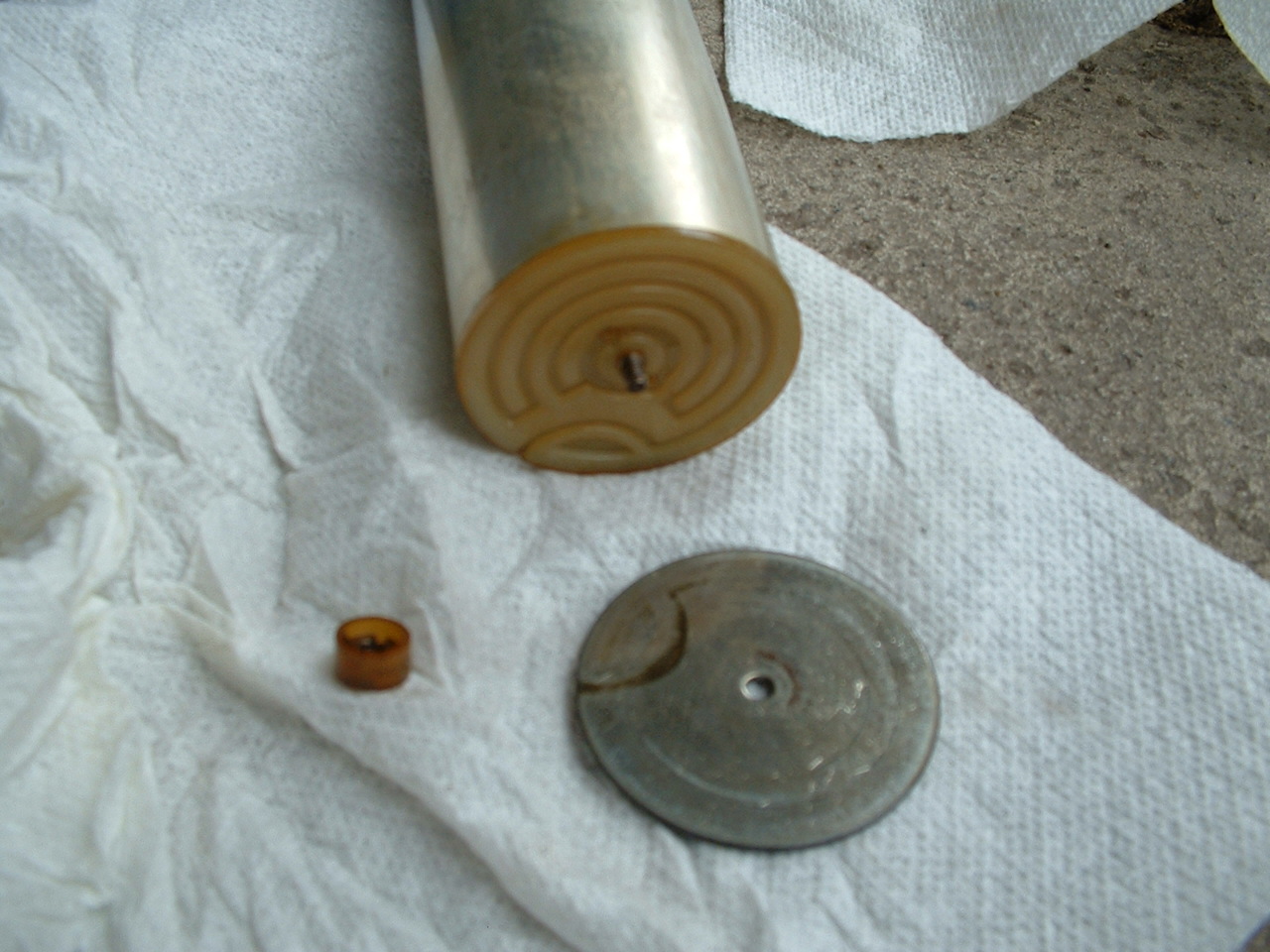 |
| Here the bottom plastic plate and surrounding tube have been removed - carefully, so as not to damage the delicate wires. Cleaning can now begin. Carburettor cleaner is used, as it is designed explicitly to dissolve fuel varnish. Brake cleaner, etc., are not as effective. The float (small cylindrical object in the middle of the sensor) is to be rinsed off, and the small silver wires are GENTLY rinsed and wiped (with a paper towel soaked in carb cleaner) to remove the varnish. There is no need to use any abrasive, as carb cleaner will remove the varnish, and any heavier work may damage the sender and break the wires. | 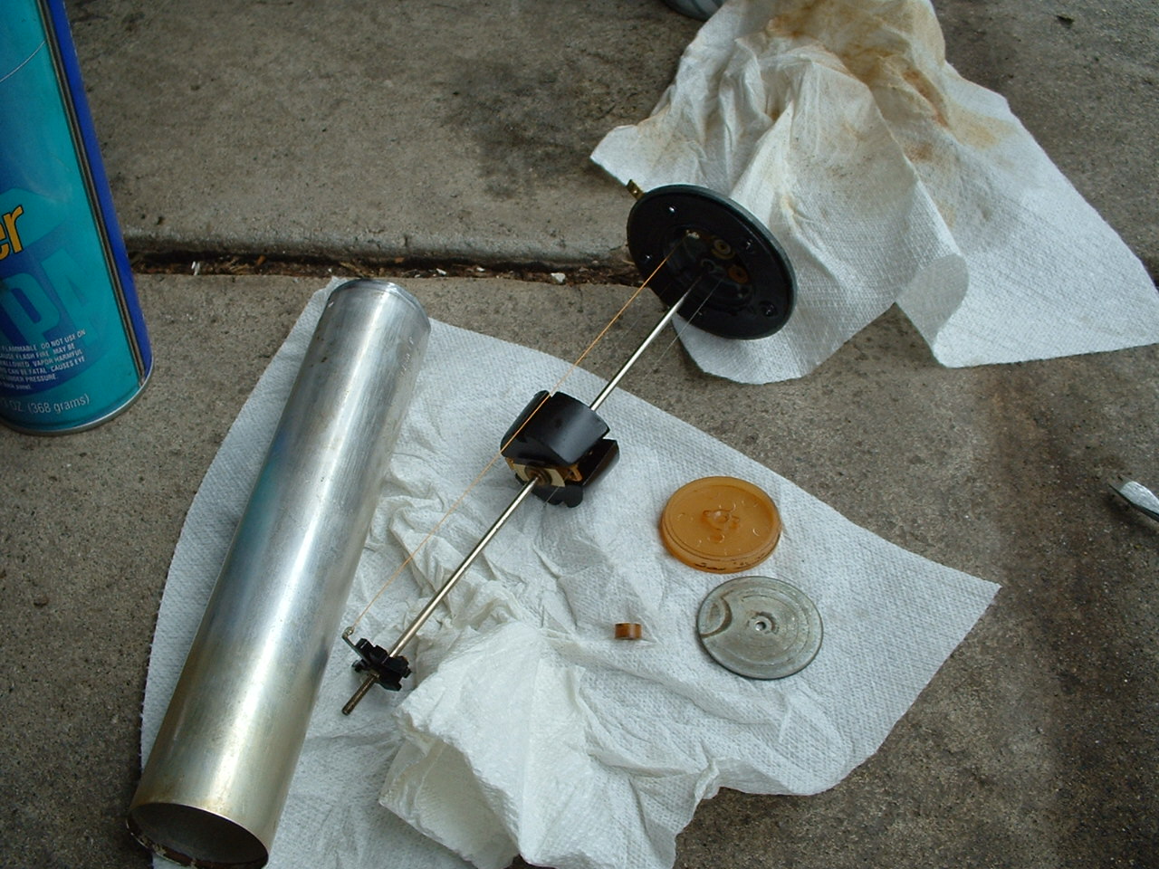 |
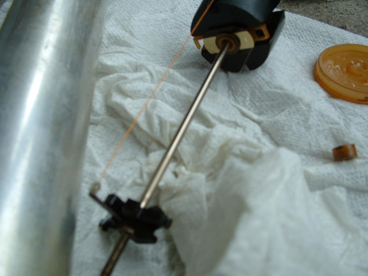
| Another close-up view to show the sender wires. As the float travels
up and down, the path for current flow changes in length (down one wire, across
the float, and up the remaining wire), thereby changing in resistance, and
altering the gauge reading. At the very bottom of travel, contacts on the float
will close another circuit, turning on the "Low Fuel" light.
Once the wires and contacts are clean, the sender is reassembled in reverse order - surround tube slides on, end plate in place and nut to secure. |
 |
| Time to test your handiwork! Hook up the wires, turn on the key, and see what the gauge reads. With the sender fully inverted, the float is at the top, as would be the case for a full tank. With the sender in it's normal orientation, connections on top, the float should be at the bottom, and the gauge should read low, with the warning light on. | 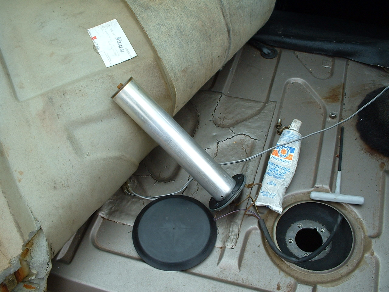 |
| Full tank! When's the last time you saw this? | 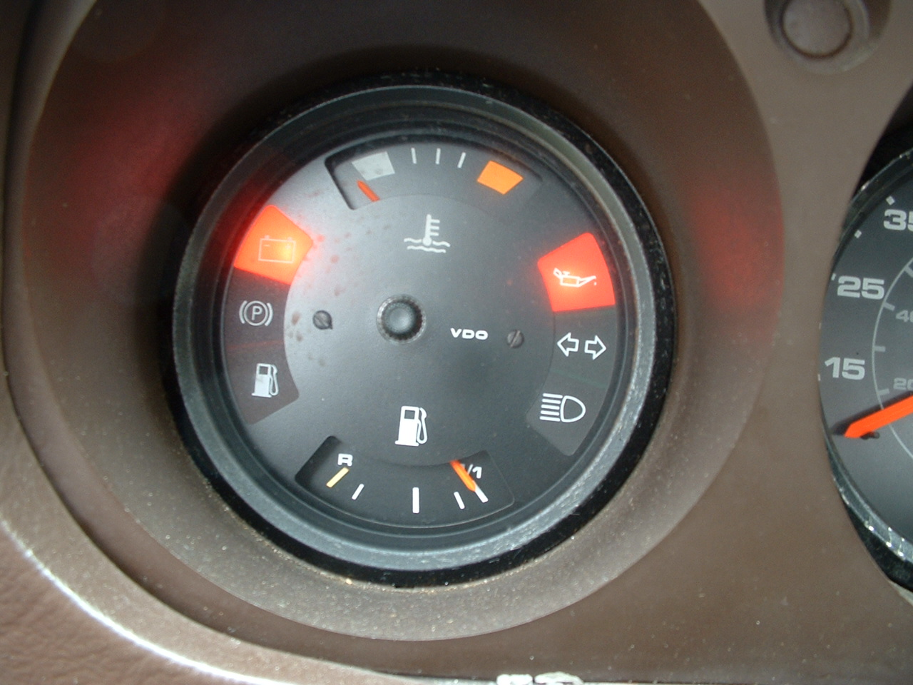 |
| And, as expected, the needle is down, and the Low Fuel light is on. Good work! | 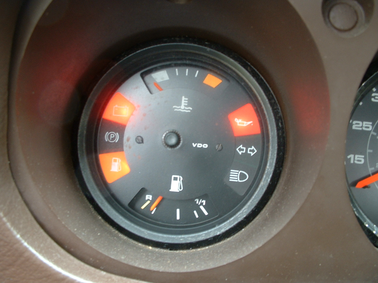 |